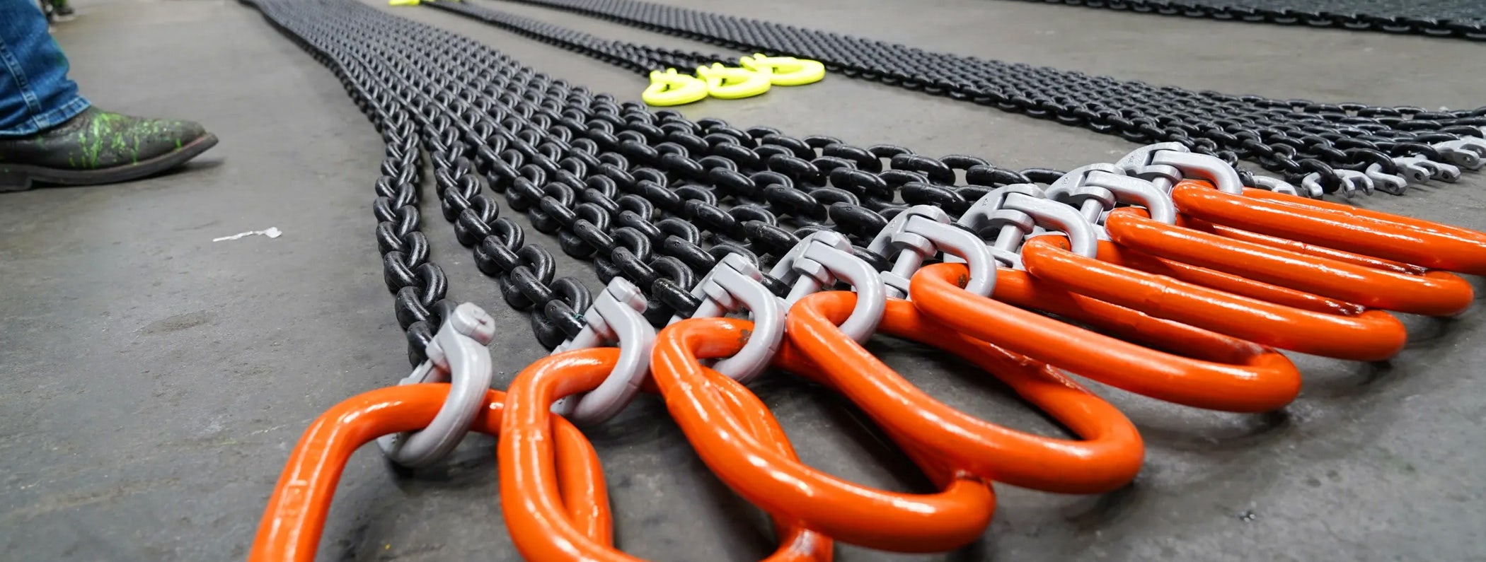
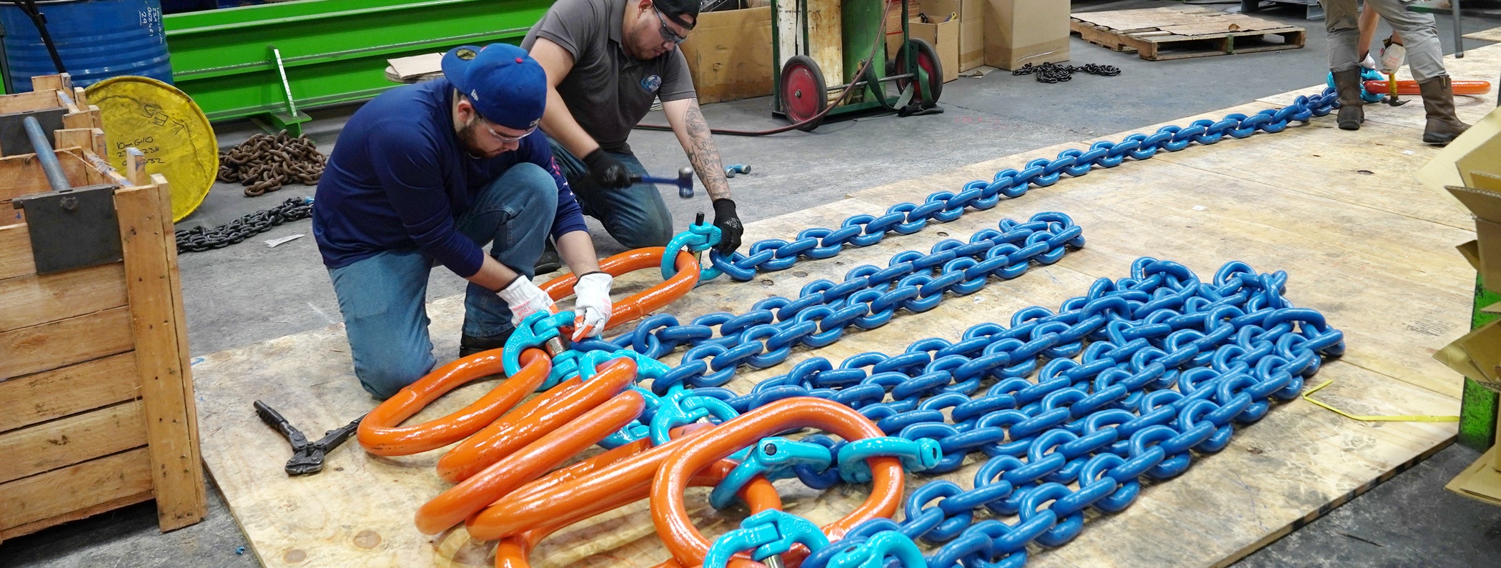
Many industries, such as construction, shipping, and manufacturing, require wire rope slings for lifting heavy loads daily, resulting in a growing demand. That’s one of the reasons why the Industrial Lifting Equipment Market valued at $72.04 billion in 2020 is projected to reach $96.11 billion by 2028.
Rope slings are made of wire strands twisted together to form a strong, flexible rope that can withstand the weight of heavy loads. However, not all slings are created equal, and choosing the wrong one can result in disastrous consequences. On the other hand, using the right wire slings for lifting can save you from deadly accidents and costly damages.
So, let's learn more about how to choose suitable wire slings for lifting.
1. Determine The Weight Capacity of Wire Rope Slings
Wire rope slings have a weight capacity, called working load limit, that you must understand and adhere to in order to ensure safety in lifting operations. You can determine the weight capacity by the strength of the wire rope, its construction, and the hardware used to assemble it.
You also need to know the weight of the load you want to lift to choose the appropriate wire rope sling capacity. You can determine this by weighing the load or calculating its weight based on its dimensions and material.
Choosing the right wire rope sling capacity is critical, as overloading can cause sling failure and potential injury or damage. This can delay your project timelines, leading to heavy financial losses.
2. Consider The Diameter, Construction, And Core of the Wire Rope
The wire rope sling capacity depends on strength, flexibility, and abrasion resistance. The diameter is the thickness of the rope, and the construction refers to the number and arrangement of wire strands used to make the rope.
Usually, strands made of larger-diameter wires are more resistant to abrasion. However, strands made of smaller diameter wires are more flexible. You can choose wire slings based on your needs.
The core of a wire rope sling can also affect its strength and durability. Be sure to select the right core for the sling, depending on the intended use. For example, a fiber core provides more flexibility, while a wire core offers greater strength.
Remember, choosing the right wire slings for lifting based on diameter, construction, and core can ensure safety and efficiency.
3. Select The Proper End Fitting for Wire Rope Slings
End fittings are devices that attach wire rope slings to the load or the lifting equipment. They include hooks, eyes, thimbles, and shackles. Each fitting has a specific use. For example, hooks connect the slings to the load, while thimbles and eyes help create a loop at the end of the slings.
Choosing the wrong end fitting can compromise the strength and integrity of the sling, leading to catastrophic accidents. The right end fitting should match the size and type of the
wire ropes, as well as the intended use and load capacity.
Here's what you need to consider:
First, consider the application, the weight, and the shape of the load.
Ensure that the end fitting is compatible with the lifting equipment.
Consult a qualified engineer or rigging professional to ensure end fitting is appropriate for the intended lifting operation.
4. Choose The Right Length of Wire Rope Slings
The length is also a critical factor in determining wire rope sling capacity because it affects the load stability and safety. Using a sling that is too short can result in insufficient support and potential failure. And if the sling is too long, it can create unnecessary weight, reducing the stability.
So, when choosing the length of wire rope slings, you should consider:
The weight and shape of the load.
The type of lifting equipment.
And the intended use.
A longer sling may be required for a bulky or irregularly shaped load, while a shorter sling may be sufficient for a compact and uniform load. But consult a qualified rigging professional if needed.
5. Assess Environmental Conditions
Environmental conditions also play a critical role in choosing the wire slings for lifting. Temperature, moisture, and corrosive substances are a few factors you need to consider. High temperatures can weaken wire ropes. On the other hand, moisture and corrosive substances can cause rust and corrosion, reducing strength.
Be sure to evaluate factors such as temperature, humidity, and exposure to corrosive substances. Consider both the immediate and long-term effects of these conditions and how they will impact the sling's strength and durability.
6. Determine The Number of Legs Required
Most wire rope slings are single-leg configurations. But you can get multi-leg slings with desired specifications. The number of legs required for a wire rope sling depends on the load's weight and shape and the desired load distribution.
Proper load distribution is essential to prevent overloading and ensure safety. A sling with inadequate legs may undergo excessive stress, resulting in sling failure.
You will need to consider the following.
The weight of the load and its shape.
Center of gravity of the load.
Also, consider the sling angle and the direction of the pull.
As you can see, heavy and bulky loads may require more legs for proper support and distribution.
7. Check for Wear and Tear
Wear and tear can significantly impact the wire rope sling capacity. Proper maintenance, including cleaning and lubrication, can also help to prevent premature wear and tear.
However, it is bound to happen over time. As it can lead to failure and accidents, you must
inspect wire ropes for damage before each use.
Here's how you can check wire slings for lifting.
Check the wire ropes for signs of damage, such as broken wires, kinks, and crushing.
Check the end fittings for any signs of deformation or damage.
Running your hands (using a glove and a cloth) along the wire ropes can help detect any hidden defects.
Remove any wire rope slings that show signs of wear and tear from service immediately and
replace them with new slings.
In Conclusion
Choosing the right wire rope slings is necessary to ensure the safety and stability of the lift. When choosing slings, you have to consider different factors, such as wire rope sling capacity, environmental conditions, proper wire inspection for wear and tear, and more. Hopefully, this post will help you choose slings as per your requirements.
Need help? You can always talk to the experts and Holloway.
Call us today to learn more about our products, or shop
online now.
Shop Online Wire Rope Slings